ROLLING ELEMENT BEARING FATIUGE LIFE TESTER CM - 9053
PURPOSE
The life of an individual rol领 bearing is defined as the number of revolutions bearing endures before the first sign of fatigue (flaking, spal领) occurs on one of its rings or rol领 elements. Purpose of this rig is to determine life of a loaded bearing. Dynamic load rating of a bearing is based on the fatigue life L10. This is the life which 90% of the bearings in a sufficiently large group can be expected to attain or exceed. When large number of identical bearings have been tested, L10 and hence, dynamic load rating can be estimated.
Any bearing which is amicable with the mounting and loading arrangement of the rig can be tested. This includes deep groove, angular contact, taper roller and cylindrical roller bearings.


DESCRIPTION
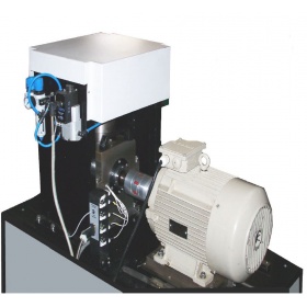
Schematic diagram of the test rig is shown in figure. Four identical bearings are mounted on a shaft. Axial and radial loads are applied when bearings are running. Failure of a bearing is sensed by abnormal increase of either vibration or temperature. At this point, the rig stops. Number of revolutions to fail are recorded.
The test rig consists of following sub-systems:
1. MECHANICAL ASSEMBLY
Each bearing size will require a matching shaft, set of spacers and adaptor rings (not shown in figure), so that they can be mounted in the housing for conducting tests. The housing is split for convenient assembly. Temperature sensors are mounted on the adaptor rings so that they touch the outer race. Vibration sensor is mounted on the housing. The ratio of the maximum to minimum bearing diameter, which can be accommodated in a test station, is 2. This is due to the load-speed requirement and dimensional constraints. Hence, the test requirements are covered in multiple test stations. Num-ber of test stations required depends on the span of test parameters. Each test station is a stand alone, independent unit.
2. LUBRICATION SYSTEM
Test bearings can be lubricated in any of the following ways:
1. Pre-packed with grease for life
2. Partial submersion in oil sump
3. Oil jet with recirculation system consisting of lubricant tank, pump, filters and delivery nozzles
3. LOADING SYSTEM
Test loads are axial and radial. Axial load is applied to the outer ring of outermost bearing on non-driven end of the shaft. This load is transmitted to the inner ring through the rol领 elements. It is then transferred to the next bearing by a spac-er, and in this manner all the bearings are loaded in series. Once axial load has been applied, radial loading starts. This procedure minimizes non-uniformity in axial loading which may arise because of frictional force due to radial load.
4. DRIVE
One end of shaft is coupled to an induction motor. Test speed is set by a variable frequency inverter. Motor and coup领 are balanced to minimize ambient vibration level of the system.
5. INSTRUMENTATION
The following sensors monitor various parameters:
? Load sensor for the measurement of axial load
? Load sensor for the measurement of radial load
? RPM sensor for test speed
? Four temperature sensors for bearing temperature at the outer ring
? Vibration sensor mounted on the housing
? Elapsed time meter
? Lube oil filter clog switch
6. MACHINE CONTROL SOFTWARE
Test rig is controlled through a PC. Machine control software facilitates preprogramming of test schedule. Test speed and radial load schedule are entered before the start of test. Speed and load can be either held constant or vary in steps or ramped when any of the bearing temperature exceeds user defined limit. Similarly, when RMS level of vibration ex-ceeds, set limit and stays continuously higher for more than one minute, a bearing is deemed to have failed, and test ter-minates. Whenever test stops, a message indicating its cause is displayed.
7. DATA ACQUISITION
Data acquisition is based on Labview 7.1. It records the following parameters:
? Axial and radial test loads
? Four channels of bearing temperature
? RMS Vibration level
Acquired data is displayed graphically online. It also monitors status of safety interlocks related to lubricating oil and loading system. When any parameters go beyond preset limit, commensurate action will be taken to ensure safety of the rig, sample and operator.
Post processing module allows viewing of the acquired data in several ways. Test results of a test can be viewed as graph. Results of several tests can be viewed together for comparison. Span of viewing can be selected and zoomed. Test results can be printed. They can also be exported to other software. The software is customized to include user’s logo, identification, address and similar information.
8. SAFETY INTERLOCKS
? Over voltage
? Under voltage
? Single phasing
? Motor over current
? Test load beyond preset limit.
? Lube oil filter clog.
? Bearing temperature exceeding preset limit.
? Vibration level exceeding preset limit.
? Safety guards
? ELCB
SPECIFICATIONS
It may not be possible to meet target specifications in one test station. Following table depicts a set of three test stations to cover 10 to 100 mm shaft diameter range. Test stations to meet your requirements may differ in number and specifica-tions.

报价:面议
已咨询5055次
报价:¥17100
已咨询242次海绵往复冲击疲劳试验机
报价:面议
已咨询759次振动分析仪

报价:¥38000
已咨询240次万能试验机

SN-T提袋疲劳试验机是对手提塑料袋进行上下振动疲劳试验的仪器

HC系列紧凑型测试系统是一个完整的测试系统,其中低噪音的液压泵充当试验机架的子结构,保持机器的占地面积最小。HC紧凑型试验机结合了液压泵的特殊降噪装置,特别适合在实验室中运行。

ZwickRoell的电液伺服疲劳试验机机架是专门为特定疲劳试验要求而设计的,这体现在其高机架刚度等方面。它们用于测定在振动载荷下的材料特性值,包括S-N试验(高周疲劳试验)、LCF试验(低周疲劳)或断裂力学试验。

设备的计量特性按中华人民共和国国家计量检定规程JJG652-90调试,符合《金属材料 疲劳试验 旋转弯曲方法 GB/T4337-2008》及《JBT 9374-1999 纯弯曲疲劳试验机 技术条件》国家标准。

PLG系列(PLG-100、PLG-200...)微机控制高频疲劳试验机,试验机主要由主机、电气控制箱、计算机等部分组成。具有完备的保护功能、试验过程可无人值守;除具有过载(110%)保护、过流保护外,还具有任意设置的交变负荷上下限保护、平均负荷上下限保护、频率保护、试验断裂保护停机;

依据GB/T18029.3及ISO7176-3标准制作,对轮椅车的制动器进行疲劳实验。本机采用液晶屏显示程序控制,可设置测试的次数,到达设定的次数自动停机,可无人看守长时间工作,操作简单,使用方便,安全稳定准确耐用。

电液伺服疲劳试验机”由主机、泵站、试验附具、全数字液压伺服控制系统及软件系统等组成,主要用于各种金属非金属的动静态性能及疲劳试验,可以进行拉伸、压缩、弯曲、高低周疲劳试验等。配置相应试验软件及试验附具后,试验机还可应用于其他各类结构件、部件的动态性能、疲劳寿命等特性测试。

电子伺服扭转疲劳试验机性能特点: 1.采用电子伺服和DDR力矩马达驱动技术,具有效率高、寿命长、噪音低、免维护的优点; 2.试验机采用“卧式结构”动态稳定性好,试验台上下件方便、随意、安全可靠; 3.不同试验所需参数一扭矩、频率、转角等可通过计算机设定,试验的进程中也可以调用和查询: 4.用户操作界面:试验软件可在Windows系统下操作,微机系统可以完成试验设定,工作状态控制,数据采集,


